voidHAL_GPIO_Init(GPIO_TypeDef *GPIOx, GPIO_InitTypeDef *GPIO_Init) { uint32_t position = 0x00u; // 记录当前初始化的是第几个管脚 uint32_t ioposition; uint32_t iocurrent; uint32_t temp; uint32_t config = 0x00u; __IO uint32_t *configregister; /* Store the address of CRL or CRH register based on pin number */ uint32_t registeroffset; /* offset used during computation of CNF and MODE bits placement inside CRL or CRH register */
/* Check the parameters */ assert_param(IS_GPIO_ALL_INSTANCE(GPIOx)); assert_param(IS_GPIO_PIN(GPIO_Init->Pin)); assert_param(IS_GPIO_MODE(GPIO_Init->Mode));
/* Configure the port pins */ while (((GPIO_Init->Pin) >> position) != 0x00u) { /* Get the IO position */ /* 记录当前初始化的是哪个管脚(二进制形式,1为初始化的管脚)*/ ioposition = (0x01uL << position);
/* Get the current IO position */ /* 中间变量,用于检查position指定的管脚是否被指定要初始化 */ iocurrent = (uint32_t)(GPIO_Init->Pin) & ioposition;
if (iocurrent == ioposition) { /* Check the Alternate function parameters */ assert_param(IS_GPIO_AF_INSTANCE(GPIOx));
/* Based on the required mode, filling config variable with MODEy[1:0] and CNFy[3:2] corresponding bits */ /* 根据输入变量生成对应寄存器的值 */ switch (GPIO_Init->Mode) { /* If we are configuring the pin in OUTPUT push-pull mode */ /* 推挽输出配置 */ case GPIO_MODE_OUTPUT_PP: /* Check the GPIO speed parameter */ assert_param(IS_GPIO_SPEED(GPIO_Init->Speed)); config = GPIO_Init->Speed + GPIO_CR_CNF_GP_OUTPUT_PP; break;
/* If we are configuring the pin in OUTPUT open-drain mode */ /* 开漏输出配置 */ case GPIO_MODE_OUTPUT_OD: /* Check the GPIO speed parameter */ assert_param(IS_GPIO_SPEED(GPIO_Init->Speed)); config = GPIO_Init->Speed + GPIO_CR_CNF_GP_OUTPUT_OD; break;
/* If we are configuring the pin in ALTERNATE FUNCTION push-pull mode */ /* 特殊功能推挽输出配置 */ case GPIO_MODE_AF_PP: /* Check the GPIO speed parameter */ assert_param(IS_GPIO_SPEED(GPIO_Init->Speed)); config = GPIO_Init->Speed + GPIO_CR_CNF_AF_OUTPUT_PP; break;
/* If we are configuring the pin in ALTERNATE FUNCTION open-drain mode */ /* 特殊功能开漏输出配置 */ case GPIO_MODE_AF_OD: /* Check the GPIO speed parameter */ assert_param(IS_GPIO_SPEED(GPIO_Init->Speed)); config = GPIO_Init->Speed + GPIO_CR_CNF_AF_OUTPUT_OD; break;
/* If we are configuring the pin in INPUT (also applicable to EVENT and IT mode) */ /* 普通输入、中断输入和事件输入 */ case GPIO_MODE_INPUT: case GPIO_MODE_IT_RISING: case GPIO_MODE_IT_FALLING: case GPIO_MODE_IT_RISING_FALLING: case GPIO_MODE_EVT_RISING: case GPIO_MODE_EVT_FALLING: case GPIO_MODE_EVT_RISING_FALLING: /* Check the GPIO pull parameter */ assert_param(IS_GPIO_PULL(GPIO_Init->Pull)); if (GPIO_Init->Pull == GPIO_NOPULL) { config = GPIO_CR_MODE_INPUT + GPIO_CR_CNF_INPUT_FLOATING; } elseif (GPIO_Init->Pull == GPIO_PULLUP) { config = GPIO_CR_MODE_INPUT + GPIO_CR_CNF_INPUT_PU_PD;
/* Set the corresponding ODR bit */ GPIOx->BSRR = ioposition; } else/* GPIO_PULLDOWN */ { config = GPIO_CR_MODE_INPUT + GPIO_CR_CNF_INPUT_PU_PD;
/* Reset the corresponding ODR bit */ GPIOx->BRR = ioposition; } break;
/* If we are configuring the pin in INPUT analog mode */ case GPIO_MODE_ANALOG: config = GPIO_CR_MODE_INPUT + GPIO_CR_CNF_ANALOG; break;
/* Parameters are checked with assert_param */ default: break; }
/* Check if the current bit belongs to first half or last half of the pin count number in order to address CRH or CRL register*/ configregister = (iocurrent < GPIO_PIN_8) ? &GPIOx->CRL : &GPIOx->CRH; registeroffset = (iocurrent < GPIO_PIN_8) ? (position << 2u) : ((position - 8u) << 2u);
/* Apply the new configuration of the pin to the register */ MODIFY_REG((*configregister), ((GPIO_CRL_MODE0 | GPIO_CRL_CNF0) << registeroffset), (config << registeroffset));
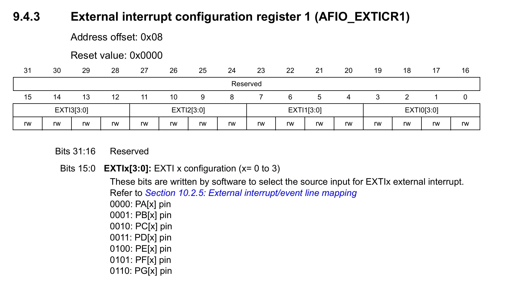
/*--------------------- EXTI Mode Configuration ------------------------*/ /* 外部中断配置 */ /* Configure the External Interrupt or event for the current IO */ if ((GPIO_Init->Mode & EXTI_MODE) == EXTI_MODE) { /* Enable AFIO Clock */ __HAL_RCC_AFIO_CLK_ENABLE(); /* EXTICR 16位 总共四个,每个EXITCR分别控制四个中断,总共 4 * 4 = 16个中断 position >> 2 ==> position / 4 ,把 0-15 转换为 0-4 即找到对应的寄存器 */ temp = AFIO->EXTICR[position >> 2u]; /* position & 3 ==> position % 4 ,即找到在当前EXITCR寄存器中,position对应的是哪一个中断。 乘4是因为左移的单位是 “中断数”,一个中断对应4位,我要左移 n个中断 意味着要左移 n * 4位。 */ CLEAR_BIT(temp, (0x0Fu) << (4u * (position & 0x03u))); SET_BIT(temp, (GPIO_GET_INDEX(GPIOx)) << (4u * (position & 0x03u))); AFIO->EXTICR[position >> 2u] = temp;
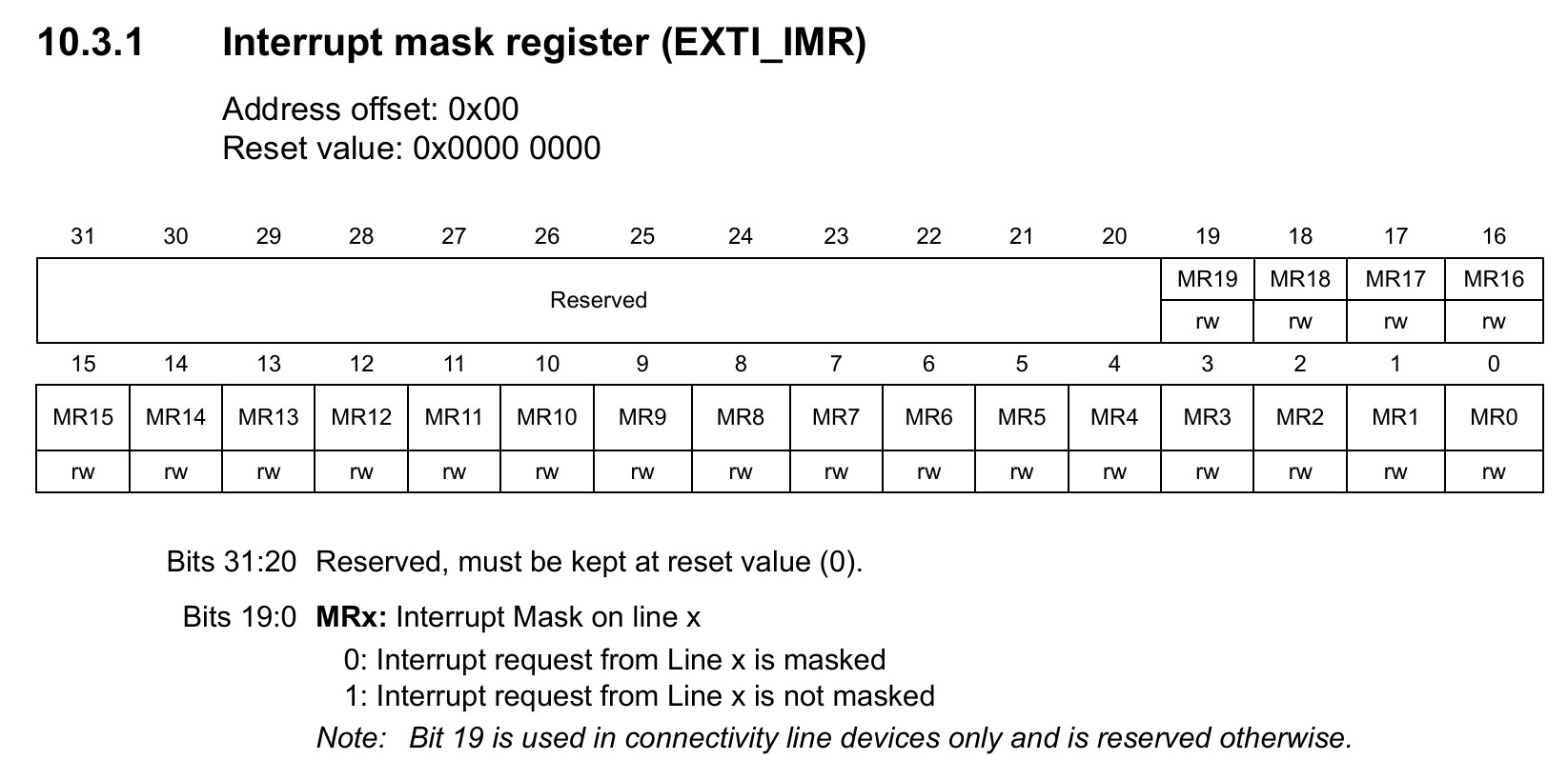
/* Enable or disable the rising trigger */ /* 设置上升沿触发 */ if ((GPIO_Init->Mode & RISING_EDGE) == RISING_EDGE) { SET_BIT(EXTI->RTSR, iocurrent); } else { CLEAR_BIT(EXTI->RTSR, iocurrent); }
/* Enable or disable the falling trigger */ /* 设置下降沿触发 */ if ((GPIO_Init->Mode & FALLING_EDGE) == FALLING_EDGE) { SET_BIT(EXTI->FTSR, iocurrent); } else { CLEAR_BIT(EXTI->FTSR, iocurrent); }